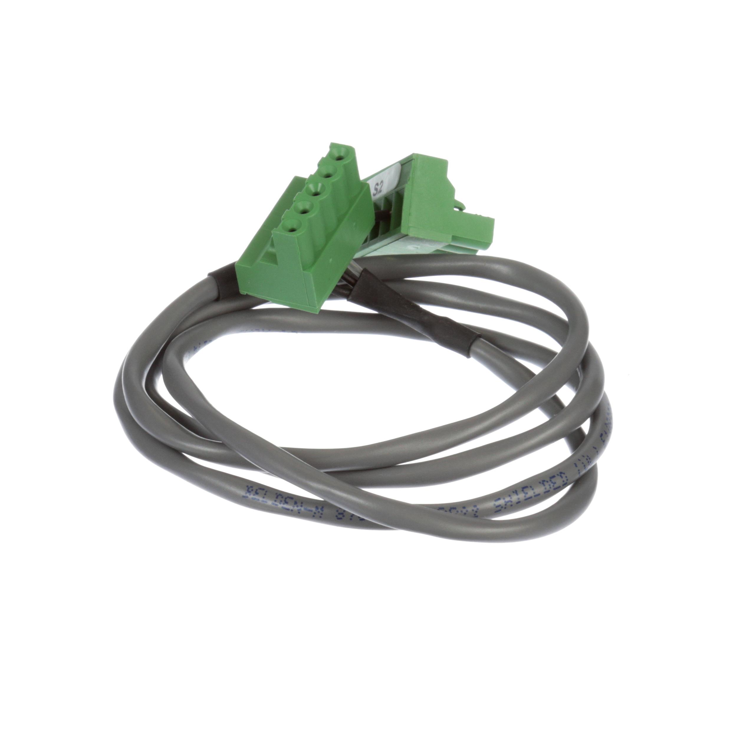
One Word: Rs485 Cable
페이지 정보
작성자 Jeff 작성일 24-07-12 15:22 조회 2 댓글 0본문
If you're sitting in the office right now, and you look to see your thermostat, there's usually RS-485 transceivers connecting that from there to basically the control unit in the building. Bus Probes are very compact (measuring only 40x36mm externally) and sport an attractive look and feel. Two Tibbo Project System (TPS), Gen. 2-compatible Tibbo BASIC applications for the setup and testing of Bus Probes are available: BP-Tester-UI and BP-Tester-Web. Each sensor has two mounting holes for attaching it to walls and other surfaces. To mount the new panels, we ordered 4 x 3.3m mounting rails and associated fixings and brackets from Dragons Breath Solar, who have been very helpful when selecting the hardware needed. To minimise shadows over the top row of panels, we decided to mount 2 on the top row and 3 below, which will give us a theoretical maximum output of 1.6kW, which is suitable for the Solis Solar 1.5kW Mini 5G Inverter. The data COM port on the base of the Solis inverter uses a small round 4-pin plug with a screw thread to hold it in place when connected. The circuit uses optical isolation (opto-coupler) to isolate your RS232 port from the RS485 cables.
We connected the A and B wires to the pins on the adapter's circuit board. We then added the 10K pull-up and pull-down resistors to the RS485 Pi board and connected it directly to the Solis inverter. Using the Solis Data Logging Stick, which uses WiFi to communicate, we were able to set up the inverter to send data to the remote soliscloud service, rs485 cable but we could not find any way to get capture data apart from scraping the basic status page built into the WiFi adapter which only gave watts being produced and daily output. Removing the WiFi adapter and connecting directly to the inverter's COM port resulted in no data again so we knew that there was something on the WiFi adapter enabling the data from the inverter. The only way to add RS232 capabilities to the Jazz PLCs is by using the MJ20-PRG programming port add-on module.

PCs are normally not equipped with an RJ11 socket for serial RS232 communications. The main difference is, that pin 1 and 6 on the RJ11 socket of the MJ20-PRG module are used as power supply. Therefore the pin assignment is a little bit different from the default pin assignment on the RJ11 socket. Those little price checkers that are kind of spread out throughout the store, you just bring your merchandise up there and just check the prices. So when you take the difference of the two, noise is actually canceled out. Because of the differential signal, any noise is subjected externally to the cable is basically subjected to both cables. So it's better noise immunity. 04), a TPS2L(G2) preloaded with the BP-Tester-UI app, and the necessary cables. 04), a Web485 board, and the necessary cables. On the Raspberry Pi, we also installed a 1-Wire Pi Plus board, and this is used with a temperature sensor fitted in the shed to monitor the air temperature, which is also posted to the MQTT server and Home Assistant. This is how we wanted to use the data with Home Assistant reading the MQTT data from the broker. From there, the data logger insures that their processes are completed at the correct parameters and can also send out alerts if the data exceeds preset levels.
After connecting as for point B, in the Settings it is possible to define a name for the device, and if the reading periodicity is less than 250 minutes, you can set an interval of hours in which the reading is not carried out / transmitted (for example you can disable the night). If we want to connect a PC with an Unitronics PLC, for example for programming or debugging reasons, we need a connection cable which is on one side fitted with a female DB9 connector, and on the other side with an RJ11 jack. The POE version makes this a single cable connection that will allow monitoring from anywhere in the world; anywhere with internet access that is. Bus Probes can be configured and tested using our web-based test app (you will need to connect the probes to your PC or Android smartphone via our Web485 board). RS485 uses two wires and sometimes a ground connection, so we used a twin-screen cable to go between the inverter to the EM112 Series Energy Meter and then onto the Raspberry Pi with a DB9 connector connected to the RS485 Pi board. The twin consists of two conductors that are twisted together.
- 이전글 The Unexplained Mystery Into PokerVIP - Online Poker Strategy Uncovered
- 다음글 Three Places To Get Deals On בניית קישורים
댓글목록 0
등록된 댓글이 없습니다.